
Quality parameters for long products
Surface quality and tight geometric tolerances are the most important criteria for the quality of long products such as wire, beams, tubes or rails. When aiming to minimize surface defects, quality engineers face two major challenges: First, the defects on the hot surface need to be detected and located. Second, the cause of the defects needs to be identified and eliminated.
But, designing measurement equipment for continuous monitoring systems in hot rolling environment imposes a number of challenges. Ambient temperature, heat radiation of the product, vibrations, dust and water are only a few examples here. Additionally, the available space for installing the equipment is often very restricted
With the two product families MEERgauge® and PROGAUGE, TBK has measurement systems available which have proven their reliability in terms of process and product data in numerous installations worldwide. The system combines dimension control and automated surface inspection within one set of measurement equipment, thus eliminating the need of two installations in the production line.
Laser light section technology
The measuring system operates based on the laser light section technology using four, eight or more sensors performing synchronous, contact-free measurements over the entire cross-section. The sensors developed by TBK measure up to 15,000 contours per second. For this purpose special lasers project lines onto the surface of the product. Cameras capture the reflected laser light and an integrated circuit converts the images into x-y-coordinates.
The coordinate values recorded by all sensors arranged around the product, represent the precise cross-section of the product. In order to capture complex contours precisely and fully, too, TBK sensors illuminate different contour regions with various laser colors to avoid interference of adjacent cameras. Thus, overlapping areas are measured precisely. This is an essential basis for synchronous measurement of each cross section, which in turn allows highest measurement accuracy and significantly reduces the effects of vibrations and lateral product movement during the measurement.


Dimension measurement and control
Based on the high-precision cross-section measurements, TBK systems generate precise information that is relevant for rolling process control and upload it back into the production system. Depending on the plant layout, the data are displayed at the plant operators’ workstations and/or is automatically analyzed by SMS group control systems with the aim of improving product quality and efficiency.
MEERgauge®
The MEERgauge® laser system for tube, bar and wire rod uses four sensors and has a scanning rate of up to 15,000 scans per second. A true-shape cross-section is created from up to 4,000 synchronous measuring points in a shared coordinate system, and is displayed with maximum precision
Unlike in conventional shadow systems, the light section system represents the true shape of the contour precisely. Furthermore, the measuring system enables closed-loop control between the contour measurement and rolling mill control systems. The computer-based interpretation of the measurement results allows roll adjustment corrections to be made while production is ongoing.
Benefits at a glance:
- High measurement data density: up to 20 million measuring points per second
- Short exposure time and absolute synchronization of the measuring sensors
- Measuring equipment in the immediate vicinity of the roll stands
- Direct transfer of measured values to the roll stand control system (closed-loop control)
- Compatible with 2-roll and 3-roll systems
- Time and cost benefits from direct production control
- More than 20 references worldwide
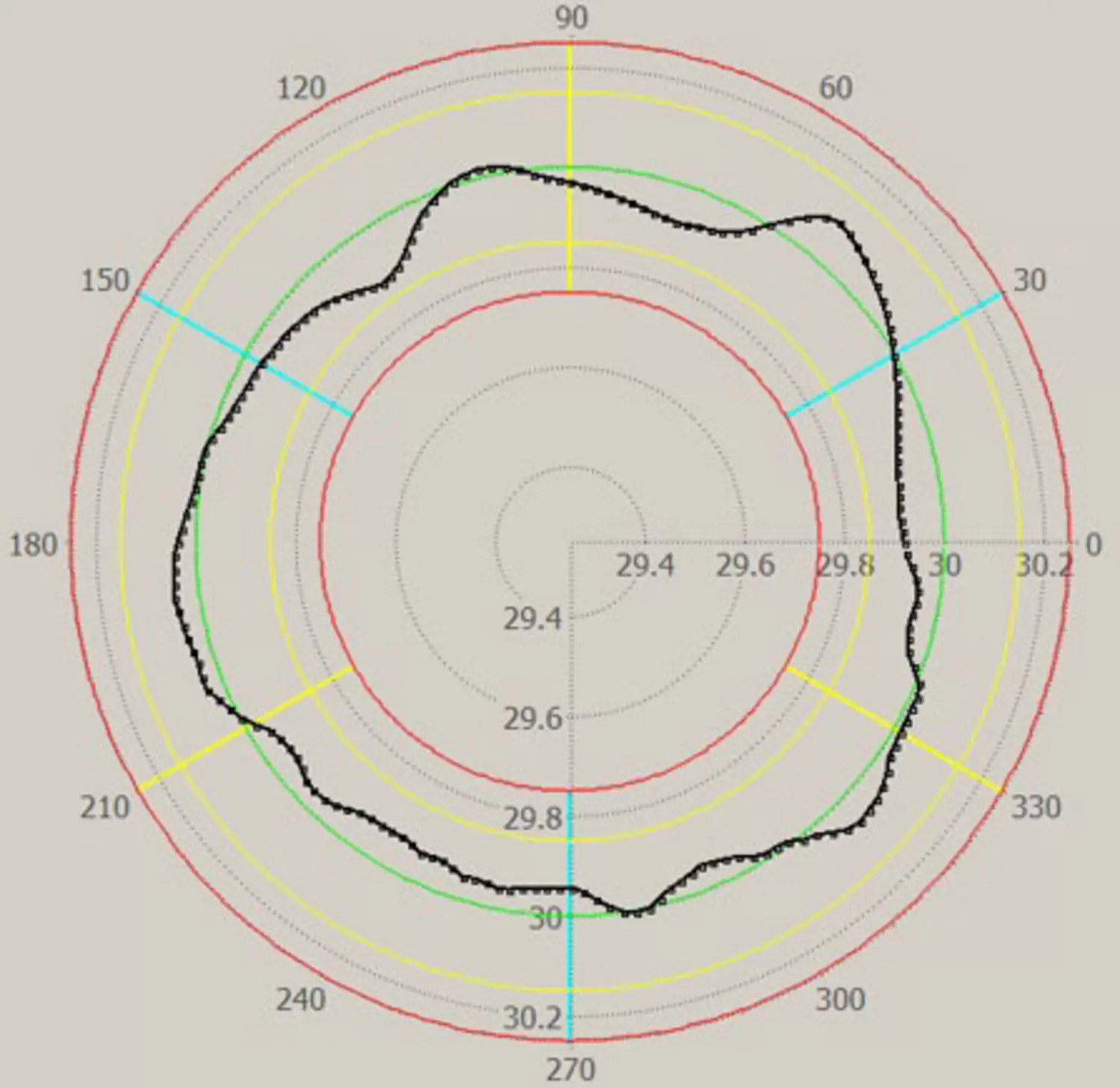
(deviation from roundness)
PROGAUGE
The PROGAUGE laser gauge for sections and rail measurement uses the laser-light section method with up to eight sensors. The various quality requirements for the individual section types (such as H/I-beam, sheet pile, vignol rail, etc.) are considered in special sets of key values, so that the system always calculates precisely the data that is relevant for the desired product quality. With particularly large formats, such as beams with web heights of over one meter, the measurement windows must be correspondingly wide. That is why top priority must be given to the alignment of the sensors in relation to each other. If required, special frame designs are created to attain the necessary size of the measurement window. Sensors with high laser capacities of up to 500 mW are included in the technology portfolio and have been applied many times
The measurement window format and the accuracy specified by the production requirements determine the number of sensors used. This means even oversized heavy sections can be reliably measured. Accurate temperature stabilization of the measuring frame is part of the system and ensures high precision measurements independent of ambient temperature variations.
Changeovers from one section type to the next are performed fully automatically, with no need for operator intervention or re-calibration. This results in significant time and cost benefits during production as well as increased plant availability.
Benefits at a glance:
- Measurement of various contours for dimensional control taking individual tolerance specifications into account
- Real-time information about complex key performance values helps operators to make appropriate process-related decisions
- Stable and precise measurement results
- Software and measuring unit are individually tailored to the production conditions
- Profiles can be changed without intervention in the measuring unit; the measurement algorithm is switched automatically
- Individually adapted laser power
- More than 30 references worldwide
Automatic surface inspection SurfTec
Based on the high-frequency cross-section measurements of the laser light section system, the surface defect detection module SurfTec is available as an add-on. In a first step, high-performance computers create a 3D model of the surface from the acquired cross-section data
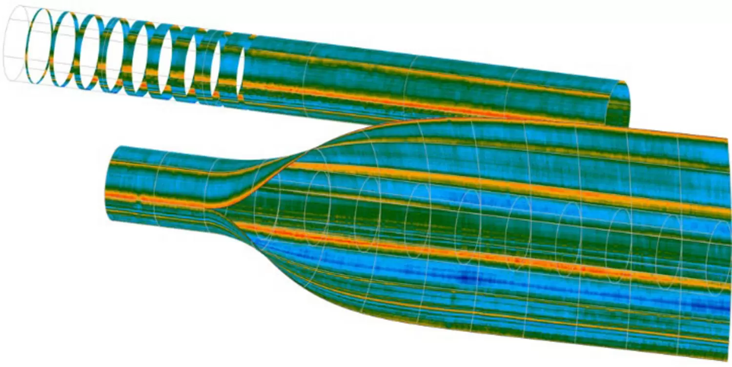
Utilizing a modified iterative-closest-point algorithm, effects of rotational and lateral movement of the product are compensated. The resulting model is visualized as a surface color map showing the deviations from the ideal contour. Additionally a rendered 3D image of the product is shown to the operator.
In the following step, the surface image is automatically scanned for surface defects. Several defect detection routines can be selected to identify and classify surface anomalies. Each class of surface defects features a different set of criteria that can be used to set the sensitivity level of the detection algorithm. All criteria are based on geometric dimensions (e.g. depth of the defect) and can be selected based on standards or customer requirements. This approach eliminates the need for time-consuming system training known from competing surface inspection systems.


In general, the following defect types are identified:
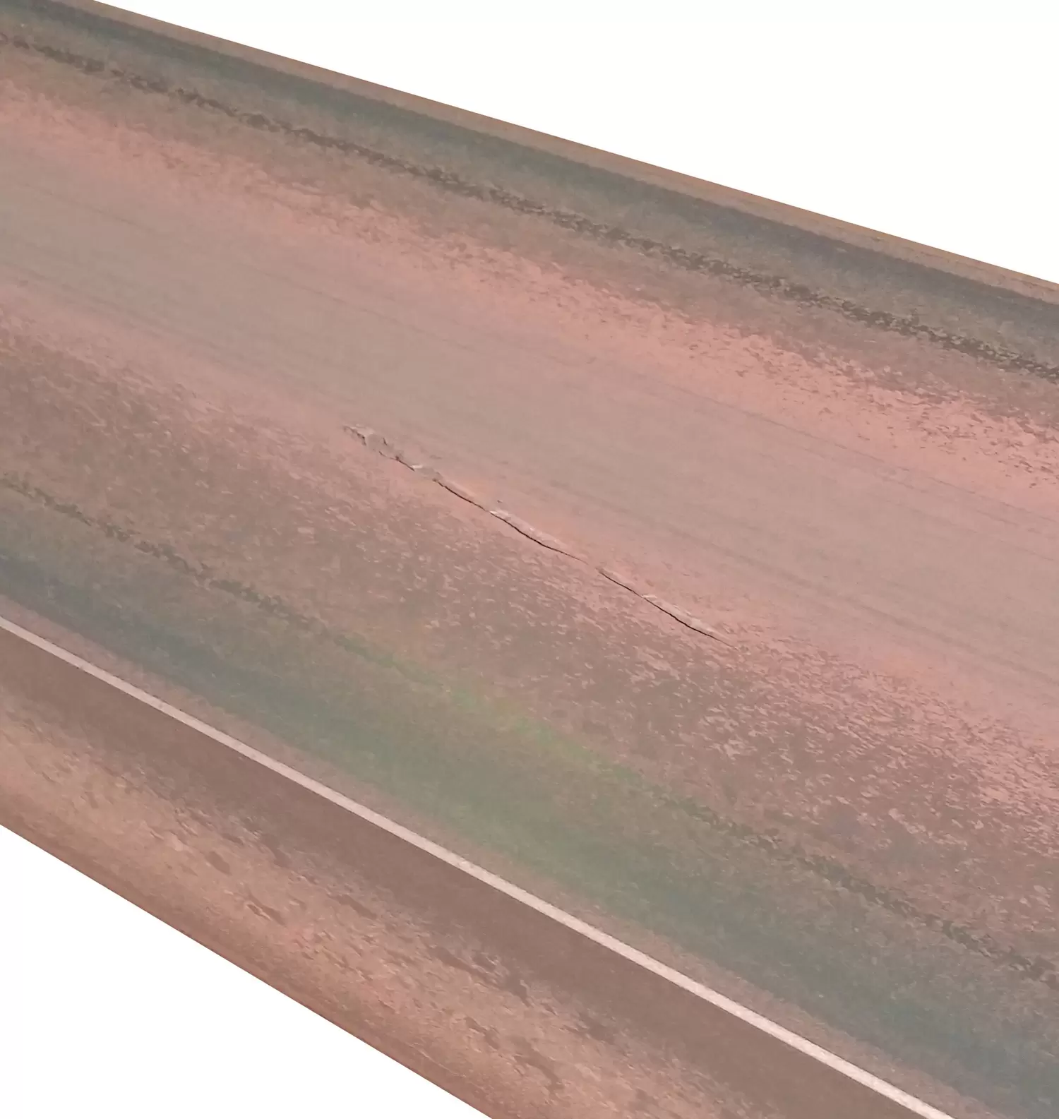
- Longitudinal defects: Anomalies that stretch over some length of the product, such as seams, grooves and long scratches.
- Periodic defects: Reoccurring anomalies (indentations or elevations on the surface) that are primarily caused by roll defects (from both guiding rolls and forming rolls).
- Defect clusters: Small-sized, locally concentrated irregularities disturbing the smoothness of the surface.
- Single defects: Individual irregularities that exceed a certain length, width, depth (or height) and volume.
SurfTec can optionally be integrated in the MEERgauge® or PROGAUGE system and helps plant operators to do both; it determines the precise position of the anomalies on the surface at the time of rolling, evaluates the data using special algorithms and provides information on the cause by classifying the defects.